1. Performance Characteristics of IC engines
Introduction
An Engine is a device which transforms the chemical energy of a fuel into thermal energy and uses this thermal energy to produce mechanical work.
- Engines normally convert thermal energy into mechanical work and therefore they are called heat engines.
- Heat engines can be broadly classified into :
i) External combustion engines ( E C Engines)
ii) Internal combustion engines ( I C Engines )
CLASSIFICATION OF INTERNAL COMBUSTION ENGINES
- There are different types of IC engines that can be classified on the following basis.
1. According to thermodynamic cycle
i) Otto cycle engine or Constant volume heat supplied cycle.
ii) Diesel cycle engine or Constant pressure heat supplied cycle
iii) Dual-combustion cycle engine
2. According to the fuel used:
i) Petrol engine ii) Diesel engine iii) Gas engine
3. According to the cycle of operation:
i) Two stroke engine ii) Four stroke engine
4. According to the method of ignition:
i) Spark ignition (SI) engine ii) Compression ignition (CI) engine
5. According to the number of cylinders.
i) Single cylinder engine ii) Multi cylinder engine
6. According to the arrangement of cylinder:
i) Horizontal engine ii) Vertical engine iii) V-engine v) In-line engine vi) Radial engine, etc.
7. According to the method of cooling the cylinder:
i) Air cooled engine ii)Water cooled engine
8. According to their applications:
i) Stationary engine ii) Automobile engine iii) Aero engine iv) Locomotive engine v) Marine engine, etc.
INTERNAL COMBUSTION ENGINE PARTS AND THEIR FUNCTION
1. Cylinder :- It is a container fitted with piston, where the fuel is burnt and power is produced.
2.Cylinder Head/Cylinder Cover:-One end of the cylinder is closed by means of cylinder head. This consists of inlet
valve for admitting air fuel mixture and exhaust valve for removing the products of combustion.
3. Piston:- Piston is used to reciprocate inside the cylinder. It transmits the energy to crankshaft through connecting rod.
4. Piston Rings:- These are used to maintain a pressure tight seal between the piston and cylinder walls and also it
transfer the heat from the piston head to cylinder walls.

5. Connecting Rod:- One end of the connecting rod is connected to piston through piston pin while the other is connected to crank through crank pin. It transmits the
reciprocatory motion of piston to rotary crank.
6. Crank:- It is a lever between connecting rod and crank shaft.
7. Crank Shaft:- The function of crank shaft is to transform reciprocating motion in to a rotary motion.
8. Fly wheel:- Fly wheel is a rotating mass used as an energy storing device.
9. Crank Case:- It supports and covers the cylinder and the crank shaft. It is used to store the lubricating oil.
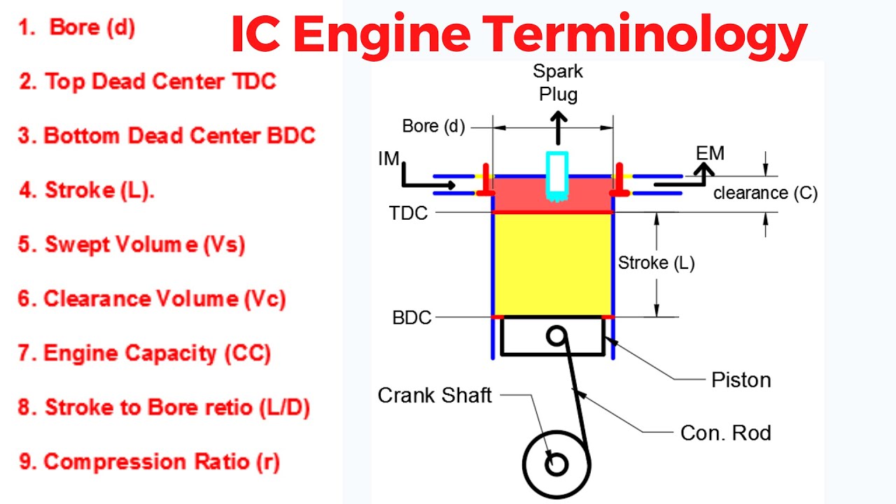
Bore: The inside diameter of the cylinder is called the bore.
Stroke: The linear distance along the cylinder axis between the two limiting positions of the piston is called stroke.
Top Dead Centre (T.D.C) : The top most position of the piston towards cover end side of the cylinder” is called top dead centre. In case of horizontal engine, it is called as
inner dead centre
Bottom Dead Centre (B.D.C):The lowest position of the piston towards the crank end side of the cylinder is called bottom dead centre. In case of horizontal engine, it is
called outer dead centre (O.D.C).
Clearance Volume: The volume contained in the cylinder above the top of the piston, when the piston is at the top dead centre is called clearance volume.
Compression ratio : It is the ratio of total cylinder volume to clearance volume.