Basics of Electrical Engineering
In this we are going to acquire the knowledge to develop the skills in Marine Electrical Technology including the regulations observed onboard ships regarding electrical equipments wherever applicable.The role of an engineer onboard a modern vessel is multifaceted and requires knowledge and application of multiple engineering disciplines. Also, almost every piece of equipment is either controlled by or fed with electrical power.Usually electrical systems ashore are seldom operated at constant load day and night and also for long periods. In the shore-based industry there are peak loads and off-peak loads; These factors have considerable effect on the life of equipment. They also may be re-modelled as new production lines and concepts are introduced or new machine tools become available. But this is not the case in the marine industry. Electrical equipment is expected to last the lifetime of the installation and of the vessel too in most cases. During this time, maximum reliability is important, particularly with regard to those services which are vital for propulsion and safety of both the ship and personnel.
Basic circuit components , current, voltage, Energy , power and its types- Basic Laws- ohms law-KCL,KVL-FLH-FRH-Faradays law of electromagnetic induction-Resistance in series and parallel combination-Basic sine wave and its parameters-Indicating Instruments-Types of Electrical Machines-D.C and A.C machines-speed control methods of both D.C and A.C Machines- Transformers.
Basic Circuit componenets: A circuit is the path that an electric current travels on, and a simple circuit contains three components necessary to have a functioning electric circuit, namely, a source of voltage, a conductive path, and a resistor.
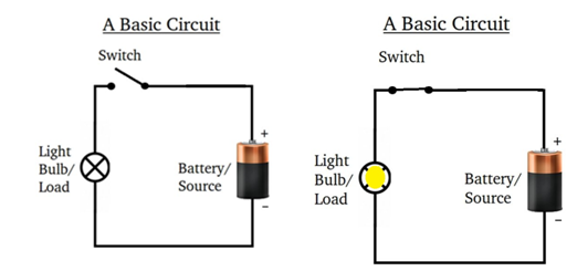
Electric Current, voltage, and resistance are three of the fundamental electrical properties. Stated simply,
• current: is the directed flow of charge through a conductor.
• Voltage: is the force that generates the current.
• Resistance: is an opposition to current that is provided by the material, component, or circuit.
Electric Current, Voltage, and resistance are the three primary properties of an electrical circuit. The relationships among them are defined by the fundamental law of circuit operation, called Ohm’s law.
As you know, an outside force can break an electron free from its parent atom. In copper (and other metals), very little external force is required to generate free electrons. In fact the thermal energy (heat) present at room temperature (220C) can generate free electrons. The number of electrons generated varies directly with temperature. In other words, higher temperatures generate more free electrons.
The motion of the free electrons in copper is random when no directing force is applied. That is, the free electrons in copper are random when no directing force is applied. That is, the free electrons move in every direction, as shown in Figure 1. Since, the free electrons are moving in every direction, this net flow of electrons in any direction is zero.
.jpeg)
When an external force causes all of the electrons to move in the same direction. In this case, a negative potential is applied to one end of the copper and a positive potential is applied to the other. As a result, the free electrons all move from negative to positive, and we can say that we have a directed flow of charge (electrons). This directed flow of electrons is called electric current.
VOLTAGE DIVIDER
Voltage Divider circuits are used to produce different voltage levels from a common voltage source but the current is the same for all components in a series cicruit

The simplest, easiest to understand, and most basic form of a passive voltage divider network is that of two resistors connected together in series. This basic combination allows us to use the Voltage Divider Rule to calculate the voltage drops across each series resistor.
CURRENT DIVIDER
Current Divider circuits have two or more parallel branches for currents to flow through but the voltage is the same for all components in the parallel cicruit

Current Divider Circuits are parallel circuits in which the source or supply current divides into a number of parallel paths. In a parallel connected circuit, all the components have their terminals connected together sharing the same two end nodes. This results in different paths and branches for the current to flow or pass along. However, the currents can have different values through each component.
- ohm’s law
Ohm’s law states that the current flowing through a conductor is directly proportional to the potential difference existing between the two ends of the conductor provided the temperature remains constant.i.e I α V, where I is the current through the conductor and V the potential difference across it.
I α V
i.e I =V × Constant
This constant proportionality equal to 1/R Where R is the Resistance of the conductor .hence as per ohm’s law ,equation relating the current flowing through a conductor and the potential applied across it , is given by, I =V/R

2) Kirchoff’s current law
This law applicable at a node of the network, which is a junction of two or more branches of that network. Kirchoff’s current law states that the sum of the current flowing towards a node is equal to the sum of current flowing away from that node that is in any network, the algebric sum of currents in all branches meeting at a node is zero. Σ I = 0
3) Kirchoff’s voltage law
This law applicable at a mesh of the circuit, which may consists of a number of branches having resistance only or a branch in addition having a source of emf. Kirchoff’s second law or voltage law states that the algebraic sum of the product of current and resistance of various branches of a closed circuit plus the algebraic sum of the emfs in that closed mesh is equal to zero. Σ I + Σ E = 0
4) An electric heater draws 8A from250v supply. What is its power rating? also find the resistance of the heater element?
P = V×I= 250×8
P =2000W
R =V/I =250/8
R =31.25Ω
5) The limitations of ohm’s law
Ohm’s law does not apply to all non-metallic conductors
It does not also apply to non-linear devices such as zener diode, vacuum tubes
Ohm’s law is true for metal conductors at constant temperature. If the temperature changes, the law is not applicable.
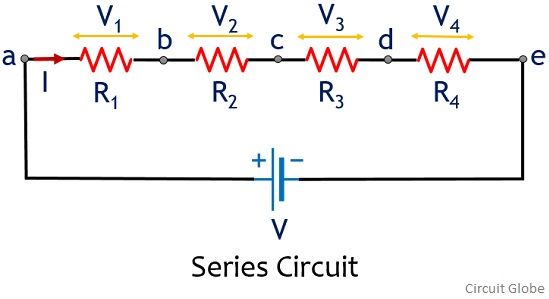
6) Series combination of resistance
- Resistors are said to be connected in "Series", when they are daisy chained together in a single line. Since all the current flowing through the first resistor has no other way to go it must also pass through the second resistor and the third and so on.
- Then, resistors in series have a Common Current flowing through them as the current that flows through one resistor must also flow through the others as it can only take one path. Then the amount of current that flows through a set of resistors in series is the same at all points in a series circuit.
8) The operating principle of MI Instrument
In this type of instrument the coil in which the current passes through is fixed. The moving iron is a flat disc, which is mounted between the fixed coils when current passes through the coil the moving iron is moved either by force of attraction or repulsion.
9) fig. Shows three resistors R1, R2&R3 connected in series to a 1V,2V&6V respectively & current passing through the circuit is 1Ma.what is the total resistance of the circuit?
Rtotal = R1 + R2 + R3 + ..... Rn etc.
Rtotal =1kΩ+2 kΩ+6 kΩ =9 Kω
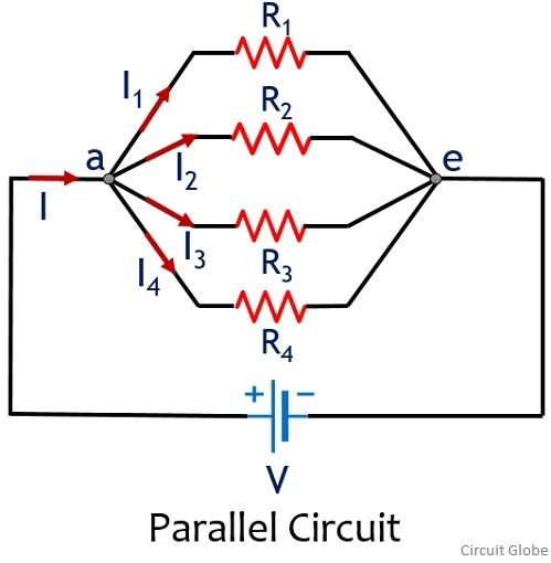
10) Parallel combination of resistance
- In parallel circuits the current can take more than one path and because there are multiple paths the current is not the same at all points in a parallel circuit. However, the voltage drop across all of the resistors in a parallel circuit is the same.
- Then, Resistors in Parallel have a Common Voltage across them and is true for all parallel elements.
11) Find the total resistance, RT of the following resistors in parallel network?
The total resistance RT across the two terminals A and B is calculated as:
1/RT =1/R1+1/R2+1/R3
1/RT = 1/200+1/470+1/220 =0.0117
RT =1/0.0117 =85.67Ω
12) Consider the following circuit with only two resistors in a parallel combination
Using our two resistor formula above we can calculate the total circuit resistance, RT as: Reff = R1R2 / R1+R2
Reff = 22×47/ (22+47) = 14985 Ω
13) A lamp rated 500 W, 100V to be operated from 220V supply. Find the value of the resistor to be connected in series with the lamp. What is the power lost in the resistor?
I=P/V=500/100=5A , Since the voltage drop across the lamp is 100V ,Voltage to be dropped in the series resistor =220-100=120V
R=V/I = 120/5=24 Ohms
Power lost in the resistor is =I2×R =600W
14) Definition of electric current
Electric current is defined as rate of flow of electric charge with respect to time.
I=dq / dt amperes
15) Resistance
The resistance is the property of conductor or circuit by which it opposes the flow of current. This parameter measured in ohms and is responsible for energy dissipation in the circuit. In other words it can be defined as the ratio of voltage to current i.e, R=V/I Ohms
16) Definition of conductance
The reciprocal resistance is called conductance. Its unit is seimen and its symbol is G
G=1/R
17) Definition of Branch and node
Branch:It is a portion of a circuit with two terminal connected to it. A branch may contain one or more elements.
Node:It is a junction of two or more branches.
18) Definition of mesh or loop
It is defined as a set of branches forming a closed path in a network.
19) Active and passive elements
Active element:
Active elements are the elements which supply power or energy to the network. Ex. Voltage source, current source
Passive element:
Passive elements are the elements which either store energy or dissipate energy in the form of heat. Ex. Capacitor and inductor=store the energy Resistor=dissipate the energy
20) Lumped and distributed network
Lumped network:
A network consisting of physically separable elements such as resistor, capacitor and inductor is known as lumped network. Ex.RLC network
Distributed network:
A network consisting of elements that are not separable for analytical purpose is known as distributed network. Ex. Transmission lines(R, L ad C is distributed along its length)
21) Bilateral and unilateral network
Bilateral network:
The voltage-currant relationship is same for current flowing in either direction is called bilateral network. Ex. R, L and C
Unilateral network:
The network has different relationships between voltage and current for the two possible directions of current. Ex: Diodes, vacuum tubes
22) Linear and non-linear network
Linear network:
The relationship between voltage and current is linear, then the network is called linear network. Ex: Resistance
Non-Linear network:
The networks which do not satisfy the linear voltage-current relationship is called non-linear network. Ex: Diodes, Zener Diodes
23) Independent source
It is defined as the source voltage independent of current flowing through it and source current independent of voltage across it. It is indicated by circle with polarity of voltage and direction of current. It is also called as uncontrolled sources. Types of independent of sources. (i)Voltage source (ii) Current source
24) Dependent sources
It is defined as the voltage source or current source depends on voltage or current elsewhere in the given circuit. It is indicated by diamond shape. It is also called as controlled sources. Types of Dependent of sources.
(i)Voltage controlled voltage source (VCVS).
(ii) Voltage controlled current source (VCCS).
(iii) Current controlled current source (CCCS).
(iv) Current controlled voltage source (CCVS).
25) Ideal voltage source
The energy source which gives constant voltage across its terminals irrespective of the current flowing through its terminal is called ideal voltage source. At any time the value of voltage at load terminals remains same.
26) Ideal current source
The current source is a source which delivers energy with a specified current which is independent of the voltage at its terminals. Such a current source which maintains a constant specified current for all voltages. “An ideal current source has infinite source impedance.
27) Differentiate between time invariant and time variant source
Time invariant source
Time invariant source which can delivers or absorb energy continuously is called time invariant source.Eg: battery, AC Generator, DC Generator. Time variant source :Time variant source is one which depends on some other quantity in the circuit which may be either a voltage or a current. Eg: Transistor, operational amplifier.
28) Compare series & parallel circuits
|
S.No. |
Series Circuit |
Parallel Circuit |
|
1 |
The total effective resistance is the sum of the individual resistance. |
The reciprocal of the total resistance is the sum of the reciprocals of individual resistance. |
|
2 |
Only one path for the current flow |
More than one path for current flow |
|
3 |
The current flow through all the resistances will be the same and equal to the total current. |
The current flowing through each resistance is different |
|
4 |
The voltage is divided across each resistance according to the value of resistance |
The voltage across each resistance is same which will be equal to the input voltage. |
|
5 |
The input voltage is equal to the sum of the voltage drops in individual resistance . |
The input current is equal to the sum of the current flowing through various resistance connected in parallel. |
29) Active & passive elements
The source of energy are called active element.
Example: voltage source, current source
The element which stores or dissipates energy is called passive element.
Example: Resistor, Inductance, Capacitor
30) Define power
The rate of doing work by electrical energy or energy supplied per unit time is called the power. Its unit is watts
P = V ´ I; P = I2R; P = E2 / R.
P = Energy / time = W/t
31) Define resistance
Resistance is the property of a substance, which opposes the flow of electric current. Also it can be considered as electric friction. Whenever current flows through a resistor, a voltage drop occurs in it and it is dissipated in the form of heat. Unit of resistance is ohm. Symbol is W measured with a help of ohmmeter.
32) Define international ohm
International ohm is defined as the resistance offered to the flow of current by a column of mercury of length 106.3cm; 14.452gm in mass with uniform cross-section at 0oC.
33) The factors affecting resistance
(i) Length – R µ L / a
(ii) Area of cross section - R µ L/ a
(iii) Nature and property of the material - R µ ρ
(iv) Conductance and conductivity – G = 1/R
34) Electrical energy
Energy is the total amount of work done and hence is the product of power and time.
W = Pt = EIt = I2Rt = E2 / Rt Joules (watt – second)
35)Voltage and current equation for a purely resistance circuit
e = Em sin wt
I = Im sin wt
Where, e, i are instantaneous value of voltage and current respectively.
Em, Im are maximum voltage and current respectively.w - Angular velocity, T – Time period.
36) Define inductance
When a time varying current passes through circuit varying flux is produced. Because of this change in flux, a voltage is induced in the circuit proportional time rate of change of flux or current i.e Emf induced a di/dt = L di/dt
Where L, the constant proportionality has come to be called as self-inductance of the circuit .The self-inductance is the property of coil by which it oppose any change of current. It is well known that the unit of inductance is Henry.
37) Define capacitance
A capacitor is a circuit element that, like the inductor, stores energy during periods of time and return the energy during others. In the capacitor, storage takes place in an electric field unlike the inductance where storage is magnetic field. Two parallel plates separated by an insulating medium form a capacitor. The emf across the capacitor is proportional to the charge in it i.e e α q or e = q/C Where, C is constant called capacitance.
38) Phase sequence
Phase sequence of polyphase system in the order on which the different phase quantities reach their maximum values.
39) Methods available for measuring power in a three phase load
(i) One wattmeter method
(ii) Two wattmeter method
(iii) Three wattmeter method
41) Define waveform
A wave form is a graph in which the instantaneous value of any quantity is plotted against time. Examples are shown in fig:
42) Alternating waveform
This is a wave which reverse its direction at regularly recurring intervals.
43) Periodic waveform
Periodic waveform is one which repeats itself after definite time interval.
44) Sinusoidal & non sinusoidal waveform
- Sinusoidal waveform is an alternating waveform in which sine law is followed.
- Non Sinusoidal waveform is an alternating waveform in which sine law is not followed.
45) Cycle
One complete set of positive and negative halves constitute a cycle.
46) Amplitude & frequency
The maximum positive or negative value of an alternating quantity is called amplitude. The number of cycles per second of an alternating quantity is known as frequency. unit is expressed as cycle/second or Hertz.
47) Time Period
Time period of an alternating quantity is the time taken to complete one cycle. Time period is equal to the reciprocal of frequency. Time period is expressed in seconds.
T=1/f (sec)
Sinusoidal Waveforms
When an electric current flows through a wire or conductor, a circular magnetic field is created around the wire and whose strength is related to the current value.

The points on the sinusoidal waveform are obtained by projecting across from the various positions of rotation between 0o and 360o to the ordinate of the waveform that corresponds to the angle, θ and when the wire loop or coil rotates one complete revolution, or 360o, one full waveform is produced.
From the plot of the sinusoidal waveform we can see that when θ is equal to 0o, 180o or 360o, the generated EMF is zero as the coil cuts the minimum amount of lines of flux. But when θ is equal to 90o and 270o the generated EMF is at its maximum value as the maximum amount of flux is cut.
Therefore a sinusoidal waveform has a positive peak at 90o and a negative peak at 270o. Positions B, D, F and H generate a value of EMF corresponding to the formula: e = Vmax.sinθ.
Then the waveform shape produced by our simple single loop generator is commonly referred to as a Sine Wave as it is said to be sinusoidal in its shape. This type of waveform is called a sine wave because it is based on the trigonometric sine function used in mathematics, ( x(t) = Amax.sinθ ).
RMS Voltage
The RMS or effective value of a sinusoidal waveform gives the same heating effect of an equivalent DC supply
Sinusoidal RMS Values

Average Voltage
The “average” or mean voltage value of a sinusoidal waveform using both the mid-ordinate rule and the analytical rule.
For a pure sinusoidal waveform ONLY, both the average voltage and the RMS voltage (or currents) can be easily calculated as:
Average value = 0.637 × maximum or peak value, Vpk
RMS value = 0.707 × maximum or peak value, Vpk
Form Factor
For a sinusoidal or complex waveform the form factor is given as: ( π/(2√2) ) which is approximately equal to the constant, 1.11. Form factor is a ratio and therefore has no electrical units. If the form factor of a sinusoidal waveform is known, then the average voltage can be found using the RMS voltage value and vice-versa as the average voltage is 0.9 times the RMS voltage value of a sine wave.
Peak factor
The peak factor of any waveform is defined as the ratio of the peak value of the wave to the rms value of the wave. Peak factor = Vp/( Vrms) =Vp/(Vp/√2)=√2=1.414.
Power Factor
In electrical engineering, the power factor (PF) of an AC electrical power system is defined as the ratio of working power (measured in kilowatts, kW) absorbed by the load to the apparent power (measured in kilovolt amperes, kVA) flowing through the circuit. Power factor is a dimensionless number in the closed interval of −1 to 1.
The “ideal” power factor is one (also referred to as “unity”). This is when there is no reactive power through the circuit, and hence apparent power (kVA) is equal to real power (kW). A load with a power factor of 1 is the most efficient loading of the supply.
That said this is not realistic, and the power factor will in practice be less than 1. Various power factor correction techniques are used to help increase the power factor to this ideal state.
Power is the capacity to do work. In the electrical domain, electrical power is the amount of electrical energy that can be transferred to some other form (heat, light, etc) per unit of time.
Mathematically power factor is the product of voltage drop across the element and current flowing through it.
Considering first the DC circuits, having only DC voltage sources, the inductors and capacitors behave as short circuit and open circuit respectively in steady-state.
Hence the entire circuit behaves as resistive circuit and the entire electrical power is dissipated in the form of heat. Here the voltage and current are in same phase and the total electrical power is given by:

Now coming to AC circuit, here both inductor and capacitor offer a certain amount of impedance given by:
The inductor stores electrical energy in the form of magnetic energy and capacitor stores electrical energy in the form of electrostatic energy. Neither of them dissipates it. Further, there is a phase shift between voltage and current.
Hence when we consider the entire circuit consisting of a resistor, inductor, and capacitor, there exists some phase difference between the source voltage and current.
The cosine of this phase difference is called electrical power factor. This factor (-1 < cosφ < 1 ) represents the fraction of the total power that is used to do the useful work. The other fraction of electrical power is stored in the form of magnetic energy or electrostatic energy in the inductor and capacitor respectively.
The total power in this case is:

This is called apparent power and its unit is VA (Volt Amp) and denoted by ‘S’. A fraction of this total electrical power which does our useful work is called active power. We denote it as ‘P’.
P = Active power = Total electrical power.cosφ and its unit is watt.
The other fraction of power is called reactive power. Reactive power does no useful work, but it is required for the active work to be done. We denote it with ‘Q’ and mathematically is given by:
Q = Reactive power = Total electrical power.sinφ and its unit is VAR (Volt Amp Reactive). This reactive power oscillates between source and load. To help understand this better all these power are represented in the form of a triangle.

Power Factor Triangle
Mathematically, S2 = P2 + Q2 and electrical power factor is active power / apparent power.
48) Phase & phase difference
i) The phase at any point on a given wave is the time that has elapsed since the quantity has last passed through zero point of reference and passed positively.
ii) Phase difference is used to compare the phase of two waveforms or alternating quantities.
49) RMS (Root Mean Square) or Effective value
Effective or RMS value of an alternating current is defined by that steady state value of current (dc) which when flowing in a given circuit for a given time produces the same heat as would be produced by the alternating current flowing in the same circuit for the same time.
50) Average value
The average value of an alternating quantity can be defined as the steady or DC current which transfer across any circuit, the same charge is transferred by that alternating current.
Average value = area under the curve over one complete cycle / Time period
51) crest (peak) factor Crest (peak) factor = maximum value / RMS value
52) power factor
The power factor is the cosine of the angle between voltage & current.
Power factor =cos (θv-θi)
Θv-------- phase angle of applied voltage
Θi--------- phase angle of current
53) Three types of power used in A.C circuit
i) Real or active power ,P=EI cosΦ
ii) Reactive power ,Q=EI SinΦ
iii) apparent power ,S=EI
54) Average or real power
The actual power consumed in an a.c circuit is called as real power. if E &I are rms value of voltage & current respectively and θ is the phase angle between E & I ,then P=EI cosΦ. The unit of real power is watts.
55) Reactive power
The power absorbed by a pure inductive reactance (XL) in an a.c circuit is called reactive power. Q=EI SinΦ. unit is VAR.
56) Apparent power
It is given by the product of rms values of applied voltage and circuit current . S=EI.the unit is volt-amperes (VA)
57) Define form factor
It is defined as the ratio between RMS value and average value
Form factor = RMS value
Average value
59) Universal instrument
The moving coil instruments are known as universal instruments, because these instruments can be used for both AC & DC
60) The errors occurred in MI instruments
i) Hysteresis error
ii) Temperature error
iii) Stray magnetic field error
iv) Frequency error due to reactance of instrument coil and eddy currents
61) Types of instruments used as ammeters and voltmeters
i) Permanent magnet moving coil ii) Moving iron iii) Electrodynamometer
iv) Hot wire v) Thermocouple vi) Induction vii) Electrostatic viii) Rectifier
62) The operating forces needed for indicating instruments
i) Deflecting force: the force required for moving the pointer from its zero position
ii) Controlling force: the force required to bring the pointer to final steady state position without overshoot and bring back the pointer to zero when deflecting force is absent
iii) Damping force: the force required to bring the pointer to find steady state position quickly without oscillations
63) The control systems used for producing control force
i) Gravity control
ii) Spring control
64) Damping system used in instruments
i) Air friction damping
ii) Eddy current damping
iii)Fluid friction damping
65) Main difference between voltmeter & ammeter
There is no fundamental difference in their operating principle. In an ammeter a current to be measured produces the deflecting torque. In a voltmeter a current, which is proportional to the voltage to be measured produces this torque. since ammeter are connected in series in the circuit, they should have a low resistance. Voltmeters are connected in parallel and their internal resistance is high.
66) Multi-range ammeter
The current range of the ammeter can be extended by connecting a number of shunts, selected by a range switch such meter is called a multi-range ammeter.
67) How is the range of voltmeter extended?
By using different range of multipliers, different full scale ranges are obtained .potential divider can also be used for the same.
68) Compensation coil in a wattmeter
By connecting a compensating coil in series with the pressure coil, the error caused by the pressure coil flowing in the current coil, can be measured.
69) The error occur in an electro dynamometer type wattmeter
i) Error due to pressure coil inductance ii) Error due to pressure coil capacitance
iii) Error due to method of inductance effect iv) Error caused by connections
v) Eddy current errors vi) Stray magnetic field errors
vii) Error caused by vibrations viii) Temperature errors
70) Why moving coil instrument are suitable only for the measurements of DC quantities?
The deflecting torque of the instruments reverses if the current reverses. If the instrument is connected AC, the pointer cannot follow the rapid reversals and the deflection corresponds to mean torque, which is zero, so these instruments cannot be used for AC.
71) What are the sources of errors that may occur in permanent magnet moving coil instrument?
i) Weakening of permanent magnets due to ageing and temperature effects
ii) Weakening of springs due to same reasons
iii) Change of resistance of the moving coil with temperature
72) The advantages & disadvantages of PMMC instrument
Advantages
- The scale is uniform
- Low power consumption
- High torque weight ratio
- Using suitable values of shunts & multipliers respectively, we can use a single instrument for many different ranges current & voltages
- Error due to stray- magnetic losses
Disadvantages
- These instrument s are useful only for DC not for AC
- The cost is higher than that of PMMC instrument
73) The principle of operation of PMMC instrument
A moving coil that carries is placed between two poles of a permanent magnet. The core around which the moving coil is wound is suspended. So that it can move freely, when current passes through the coil, it produces magnetic field .the permanent magnet also produces magnetic field the deflecting torque is produced due to the interaction between two fluxes. Since the permanent magnet is fixed, the moving coil tends to move and the pointer which is one of the part moving coil arrangement also moves.
74) The principle of energy meter
On production of eddy currents in the moving system by the alternating fluxes. These eddy currents induces in the moving system interact with each other to produce a driving torque due to which disc rotates to record the energy
75) The major parts of energy meter
i) Driving system ii) Moving system iii) Braking system iv)Registering system
78) A 150W, 230V bulb is put in series with a 30W, 230V bulb across a 450V supply. What will be current drawn? What is the power consumed by each bulb?
80) A parallel network consists of three resistors of 2W, 4W and 8W.If the current in the 4W resistor is 4A.What are the currents in other resistors?
81. The 3 basic rules of Electricity?
Rule 1 – Electricity will always want to flow from a higher voltage to a lower voltage.
Rule 2 – Electricity always has work that needs to be done.
Rule 3 – Electricity always needs a path to travel.
82. Electricity
Electricity is the presence and flow of electric charge. ... It is a form of energy which we use to power machines and electrical devices. When electrical charges are not moving, electricity is called static electricity
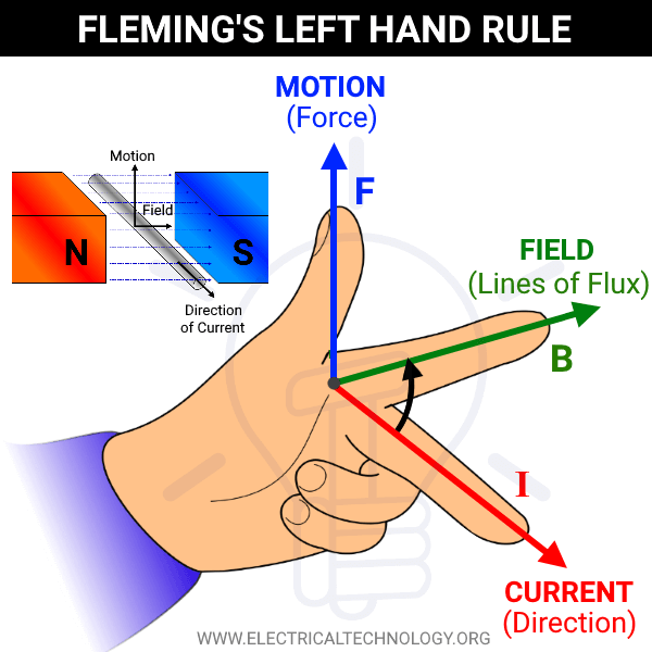
83. Fleming’s Left Hand and Right Hand Rule.
Whenever a current carrying conductor comes under a magnetic field, there will be a force acting on the conductor. The direction of this force can be found using Fleming’s Left Hand Rule (also known as ‘Flemings left-hand rule for motors’).
Similarly if a conductor is forcefully brought under a magnetic field, there will be an induced current in that conductor. The direction of this force can be found using Fleming’s Right Hand Rule. Fleming’s Left-Hand rule is mainly applicable to electric motors and Fleming’s Right-Hand rule is mainly applicable to electric generators.

84. Faraday’s Law
Faraday’s law of electromagnetic induction (referred to as Faraday’s law) is a basic law of electromagnetism predicting how a magnetic field will interact with an electric circuit to produce an electromotive force (EMF). This phenomenon is known as electromagnetic induction.
85. 
Any change in the magnetic field of a coil of wire will cause an emf to be induced in the coil. This emf induced is called induced emf and if the conductor circuit is closed, the current will also circulate through the circuit and this current is called induced current.
Method to change the magnetic field:
- By moving a magnet towards or away from the coil
- By moving the coil into or out of the magnetic field
- By changing the area of a coil placed in the magnetic field
- By rotating the coil relative to the magnet
86. Faraday’s Second Law
It states that the magnitude of emf induced in the coil is equal to the rate of change of flux that linkages with the coil. The flux linkage of the coil is the product of the number of turns in the coil and flux associated with the coil.
87. The types of electrical machines
Electrical machines are classified as AC machines and DC machines.
Types of DC machines
1. DC Generator 2. DC Motor
Types of AC machines
1 Alternator
2. Synchronous motor
3. Induction motor
(a) Single phase (b) three phase
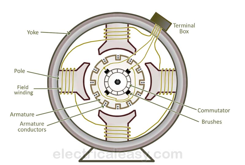
88. The different parts of a d.c generator.
The different parts of dc generator are
-
- Magnetic frame (or) yoke.
- pole core and pole shoes
- pole coil or field coils
- armature windings or conductors
- armature coils
- commutator
- Brushes and bearing.
89. The principle of operation of dc motor
An electric motor is a machine which converts electric energy into mechanical energy. The motor action is based on the principle that when a current carrying conductor is placed in a magnetic field, it experiences a force whose direction is given by Fleming’s left hand rule and the magnitude is given by F= BIL Newton.
video Link https://www.youtube.com/watch?v=E9X_ZQDt670
90.Mention the two types of armature winding. What is the number of parallel Paths in each case?
Type of winding
- lap winding
- wave winding
A, No of parallel paths
A= P for lap winding
A= 2 for wave winding
91. Back emf
If the voltage is applied and current is passing in the armature, the motor starts rotating. At that time armature conductors also rotates and hence cuts the flux. Due to that an emf is induced in the armature and the direction is found to be opposite to that of the supply this is known as back emf. Eb = -V
91. The emf equation of DC generator
Generator emf, Eg = ØZNP/60 A volts
Where Ø - is the flux per pole in wb
Z- is the total number of armature conductors
N- is the speed of armature is rpm
P- is the no of poles
92. Obtain an expression for armature torque
Let Ta be the torque developed by the armature of a motor running at N rpm. If Ta is in N-m, the power developed
P= EbIa watts
Equation 1) and 2) we get
T a = 0.159Ø Z Ia (P/A) N-m
Where, Eb = ØZN (P/A) volts.
93. The use of inter poles in a DC machines
The uses of inter poles in a DC machines are
- The commutating or reversing emf generated in the interpoles neutralizes the reactance emf and thereby making commutation sparkles
- It neutralizes the cross-magnetizing effect of armature reaction. Hence brushes are not to be shifted from the original position.
94. The methods of improved commutation
The methods of improving commutation are
- Resistance commutation
- EMF commutation
- Interpoles or compoles
speed control methods of both D.C and A.C Machines- Transformers.
There are three general methods of speed control of D.C. Motors.
- Resistance variation in the armature circuit: This method is called armature resistance control or Rheostat control.
- Variation of field flux Ф This method is called field flux control.
- Variation of the applied voltage
The relationship given below gives the speed of a D.C. motor
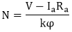
The above equation shows that the speed depends upon the supply voltage V, the armature circuit resistance Ra, and the field flux Ф, which is produced by the field current. In practice, the variation of these three factors is used for speed control. Thus, there are three general methods of speed control of D.C. Motors.
- Resistance variation in the armature circuit: This method is called armature resistance control or Rheostat control.
- Variation of field flux Ф
This method is called field flux control. - Variation of the applied voltage.
This method is also called armature voltage control.
1. Armature resistance control (Rheostat Control):

Figure: (a) Speed control of a d.c. Shunt motor by armature resistance control.
(b) Speed control of a D.C. Series motor by armature resistance control.
In this method, a variable series resistor Re is put in the armature circuit. The figure (a) above shows the process of connection for a shunt motor. In this case, the field is directly connected across the supply .
Speed Control of Shunt Motors
- Flux control method
- Armature and Rheostatic control method
- Voltage control method
- Multiple voltage control
- Ward Leonard system
Speed Control of Series Motors
- Flux control method
- Field diverter
- Armature diverter
- Trapped field control
- Paralleling field coils
- Variable Resistance in series with motor